Sunday, November 18, 2012

Industry Day.

Assalamualaikum w.b.t.

Finally, the day had come! Alhamdulilah I managed to finish my final year project.! First and foremost, I would like to express my heartily gratitude to my supervisor, Madam Siti Afifah binti Mohshim for the guidance and enthusiasm given throughout the progress of this project. My appreciation also goes to my family who has been so tolerant and supports me all these years. Thanks for their encouragement, love and emotional supports that they had given to me. In preparing this report, I was in contact with many people, researches, academicians and practitioners. They have contributed towards my understanding and thoughts.


Final Touch Up

Assalamualaikum w.b.t

its 2 days more before the industry day. so for today I have to complete all the frameworks. because of fully concentration I forgot to snap all the steps. after finished the projects then i realized that i did not snap any single pictures! huuu.. i'm so careless.. my bad. 


 the final touch up.

Result

Assalamualaikum w.b.t


Besides the programming, this study also examines how the ultrasonic sensors functions. All the data are gathered presented in Table 3. The table shows analysis of the ultrasonic Sensor analog voltage value between the calculation value and measurement value. Figure 24 illustrate the concepts of the calculation which is followed with the formulas.

Table 3: Result of analyzing the ultrasonic sensor

No
Range (cm)
Calculation (mV) 1 inch= 10mV
Measured (mV)
Error %
1
0
0
0
0
2
5
50
42
16
3
10
100
94
6
4
15
150
142
5.3
5
20
200
193
3.5
6
25
250
245
2.0
7
30
300
296
1.3
8
35
350
346
1.1
9
40
400
396
1.0


Figure 24: Square Wave Oscillation

Figure 24 shows the usual square wave. In each time interval, the waves repeat regularly because they are stable. The waves commute between V- and V+, stop at every stage of running time (Ta or Tb). Therefore, t is the addition of Ta and Tb.
T = Ta + Tb
Where
            T is the period of the square wave
            Ta is the interval between T1 and T2
            Tb is the interval between T2 and T3
            For frequencies,
            T = (1/F) = 0.69 C1 [2R1 + (R2+R3)]


By using the formula above, duty cycle can be found through the calculation steps as follows:

T off = 0.69C1
T on = 0.69C1 (R1 +R2+R3)
Duty cycle = (T on / T)
Duty cycle = (R1+R2+R3) / [(R2+R3) +2R1]


            In Table 3, the voltage values obtained from the test are slightly different from the values shown in the ultrasonic sensor data sheet. It shows that there were errors with the ultrasonic analog output by. In relation, Figure 25 shows the difference between calculation value and the measured value.


Its Working!

After a month struggle to create the program finally its worked! Alhamdulilah.. :)


Design Process

Assalamualaikum w.b.t

After confirm the circuit, next step are design process. The design process is based on the architecture. Basically the ultrasonic path planning functions like ordinary blind canes. The difference is that the Ultrasonic path planning is equipped with ultrasonic sensor and circuit box can be placed.
There are a few circuits designed. Firstly the design was tested on the diptrace is finalized, printed circuit board (PCB) was fabricated. The important element when designing the PCB is the size of the PCB which is long rather than wide. It is also to make sure that the design of ultrasonic path planning is small as possible. 


Arduino Uno on PCB with AD622 and 7660s. (top view)


Bottom view
After sizing and remove the serial monitor, AD622 and 7660s. 


Thursday, September 20, 2012

Development and Installation of Ultrasonic Path Planning for the Blind Person

Assalamualaikum w. b.t

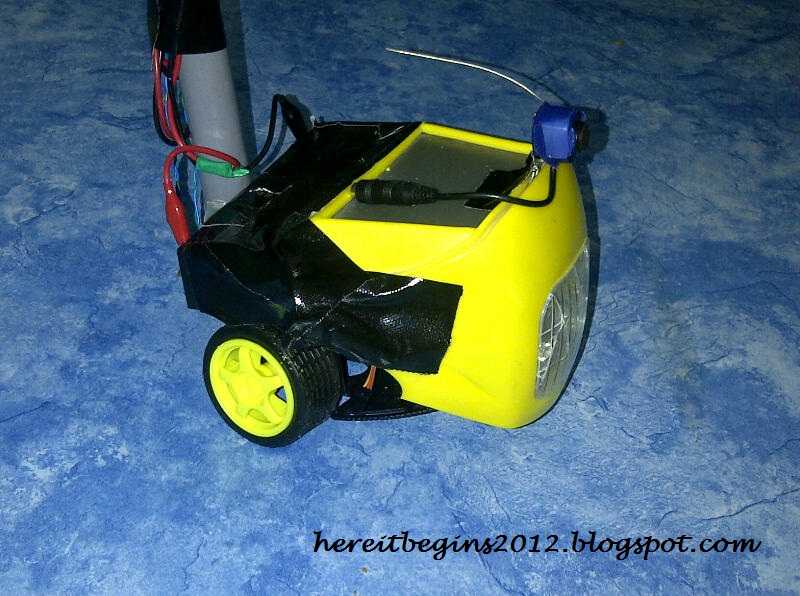
So for today, I had assemble the circuit. I had build the circuit for avoiding object.


For the testing, I had used this code:

//author: rabia'tul adawiyah roslan
//projects name: ultrasonic path planning for the blind person

// variables to take x number of readings and then average them
// to remove the jitter/noise from the DYP-ME007 sonar readings
const int numOfReadings = 10; // number of readings to take/ items in the
array
int readings[numOfReadings]; // stores the distance readings in an array
int arrayIndex = 0; // arrayIndex of the current item in the
array
int total = 0; // stores the cumlative total
int averageDistance = 0; // stores the average value
// setup pins and variables for DYP-ME007 sonar device
int echoPin = 2; // DYP-ME007 echo pin (digital 2)
int initPin = 3; // DYP-ME007 trigger pin (digital 3)
unsigned long pulseTime = 0; // stores the pulse in Micro Seconds
unsigned long distance = 0; // variable for storing the distance (cm)
// setup pins/values for LED
int redLEDPin = 9; // Red LED, connected to digital PWM
pin 9
int redLEDValue = 0; // stores the value of brightness for the
LED (0 = fully off, 255 = fully on)
//setup
void setup() {
pinMode(redLEDPin, OUTPUT); // sets pin 9 as output
pinMode(initPin, OUTPUT); // set init pin 3 as output
pinMode(echoPin, INPUT); // set echo pin 2 as input
// create array loop to iterate over every item in the array
for (int thisReading = 0; thisReading < numOfReadings; thisReading++) {
readings[thisReading] = 0;
}
// initialize the serial port, lets you view the
// distances being pinged if connected to computer
Serial.begin(9600);
}
// execute
void loop() {
digitalWrite(initPin, HIGH); // send 10 microsecond pulse
delayMicroseconds(10); // wait 10 microseconds before turning off
digitalWrite(initPin, LOW); // stop sending the pulse
pulseTime = pulseIn(echoPin, HIGH); // Look for a return pulse, it should be high
as the pulse goes low-high-low
distance = pulseTime/58; // Distance = pulse time / 58 to convert to
cm.
total= total - readings[arrayIndex]; // subtract the last distance
readings[arrayIndex] = distance; // add distance reading to array
total= total + readings[arrayIndex]; // add the reading to the total
arrayIndex = arrayIndex + 1; // go to the next item in the array
// At the end of the array (10 items) then start again
if (arrayIndex >= numOfReadings) {
arrayIndex = 0;
}
averageDistance = total / numOfReadings; // calculate the average distance
// if the distance is less than 255cm then change the brightness of the LED
if (averageDistance < 255) {
redLEDValue = 255 - averageDistance; // this means the smaller the distance the
brighterthe LED.
}
analogWrite(redLEDPin, redLEDValue); // Write current value to LED pins
Serial.println(averageDistance, DEC); // print out the average distance to the
debugger
delay(100); // wait 100 milli seconds before looping
again
}

Wednesday, September 5, 2012

Week 3 ( FYP 2)

Assalamualaikum.

On this week, I just upgrade the looks of my project. I add the light at the robotic base. my purpose to put this light is to make the people around the blind people alert that he or she exist in the surrounding. I am still thinking whether it suitable to put some sound like buzzer or not.


Week 2 (FYP 2)

Assalamualaikan w.b.t.

Alhamdulilah, my ultrasonic sensor was received! Yeay me! Thank you Mr Azmi from Myduino.com. So I can continue to test my sensor and start build the circuit and combined it with the sensor. If I have done this circuit and sensor completely, InsyaAllah my project automatically done.. So now I need to study, learn, practice and do the programming process.


Week 1 (FYP 2)

Assalamualaikum.

On July 29th I was registered as semester 7 student also automatically as FYP 2 student. For this 1st week I just bought the add on hardware to complete the framework of my project.


the plastic cover to hide wires or to makes it orderly. 

the black box which to create orderly switch

Wednesday, June 27, 2012

Semester Break part II

On the 2nd week stayed at my uncle house, I started set up the hardware. For this time, I learned how to build the hardware and make it run manually. I was half completed the framework of my projects. At this time my projects just can run left, right, front and back. The ultrasonic sensor I can't order it yet cause of out of stock. Encik Azmi (myduino.com) told that maybe on the next week he would restock the sensor. I had waiting for the new registration. So after new registration I can meet my supervisor to discuss more and start the next stage which is build the program, test and complete my projects.


Semester Break

Its semester break now. Semester break starts on 17th may 2012 untill 27th july 2012. On the 1st week,  I went to the Kolej Mara Kuala Nerang as a Secretariat for "Program Bersama Alumni Foundation UniKL FIST batch 9 2012/2013" under Center of Foundation UniKL that held 4 days 3 nights.


After 3 weeks of rest, I had decided to go to my uncle house for starts my learning session with my uncle. For your information my uncle who is lecturer electronics at KKTM Ledang. I had stayed at his house for 2 weeks. In 2 weeks I had learned the basic to build the hardware and test the hardware. This learning session, gave me a lot of information and gave me understanding how to do my project. Its easier to me to understand how the circuit run, how to connect the circuit and the sensor together when I need to do my project with my supervisor later on.

On the 1st week stayed, I starts with buy the hardware components:


learned the specification of arduino mobile platform:


New Updates..!

Its been a while I did not update my FYP blog. sorry for the late. I had been busy with my FYP 1 presentation, assignments on clinical mini projects and get focus to my final examination. Alhamdulilah I had go through all the presentation, mini projects and final examination well. the result for my FYP 1 was good. Syukur, thanks to Madam Sabrina, Sir Syazwan and Madam Hajar. For my project progress I will update in new entry. 

Sunday, April 8, 2012

Part 10 (Week 10)

Assalamualaikum w. b.t

On the previous entry (The Components) I had mentioned that I will use Roboduino Romeo. But after discussed with my advisor and Sir Zul, we found that the Roboduino Romeo not compatible to my project cause of the output produced. Robuino Romeo is suitable to projects that have more output such as robot. As for my project just perfect to do it with arduino uno. So I have to exchange the part of components.

Description of Arduino Uno:

This is the new Arduino Uno R3. In addition to all the features of the previous board, the Uno now uses an ATmega16U2 instead of the 8U2 found on the Uno (or the FTDI found on previous generations). This allows for faster transfer rates and more memory. No drivers needed for Linux or Mac (inf file for Windows is needed and included in the Arduino IDE), and the ability to have the Uno show up as a keyboard, mouse, joystick, etc.

The Uno R3 also adds SDA and SCL pins next to the AREF. In addition, there are two new pins placed near the RESET pin. One is the IOREF that allow the shields to adapt to the voltage provided from the board. The other is a not connected and is reserved for future purposes. The Uno R3 works with all existing shields but can adapt to new shields which use these additional pins.

Arduino is an open-source physical computing platform based on a simple i/o board and a development environment that implements the Processing/Wiring language. Arduino can be used to develop stand-alone interactive objects or can be connected to software on your computer (e.g. Flash, Processing, MaxMSP). The open-source IDE can be downloaded for free (currently for Mac OS X, Windows, and Linux).

Features:

  • ATmega328 microcontroller
  • Input voltage - 7-12V
  • 14 Digital I/O Pins (6 PWM outputs)
  • 6 Analog Inputs
  • 32k Flash Memory
  • 16Mhz Clock Speed

Friday, April 6, 2012

Arduino Workshop

Assalamualaikum w.b.t

On the 23rd Feb 2012, Medical Electronics Club was held “Let’s Talk Arduino” by Sir Zulkifli Mahmoodin. The talk was held to introduce the Arduino as microcontroller. Before this, we just hear PIC, but now we have the Arduino as microcontroller which very easy compared PIC. I had joined that talk.

After got highly demand to extend the talk, Sir Zulkifli Mahmoodin elate to extend the talk became "Arduino Workshop". After discussing with the Medical Electronics Club committees, Sir Zul agreed to held Arduino Workshop on 17th March 2012.

In this workshop, Sir Zul had teach us manually, technically step by step how to use arduino. Set up the programming and applied the arduino program.

A month

Assalamualaikum w.b.t

It’s been a month already I didn't update my blog. Sorry for the late update. I had been busy with my phase test on week 7, assignments and mini project. I had to sit 5 papers for the phase test. Alhamdulilah, I can go through the phase test successfully.

So for week 6 until week 8, my advisor asks me to do more research about my project. Search the old research by others. Read and understand how they done and how I can improve the project much better and more efficient. I get the information from surfing the internet and some journals. Here the examples:

  • Ø Sensing cane can help blind people avoid obstacle at eye level.

Associate professor Mitsuhiro Okayasu at the Akita Prefectural University in Japan has designed an electronic cane that will help blind people sense obstacles in their path at the level of their eyes.

The device features two ultrasonic sensors situated inside the cane where the person holds it and helps the user identify objects both in front and above him.The grip will vibrate when the cane encounters obstacles in front, while a wristband worn by the user will vibrate when the obstacle lies above him. Both sensors can detect obstacle from 1 ½ meters away. The cane is light, weighing about 300 grams.

  • Ø A cane for the bind improves social interactions, Sunday Strolls.

Design student Selena Chew has a more modest technological breakthrough to help 285 million people who are blind or partially blind. The BlindSpot cane a clever and empathetic technological attempt to create new opportunities for social interaction for the visually impaired by harnessing GPS technology and non-visual interface design.

“I took the approach to serve their emotional needs more than just their physical needs,” she says. So, for her design program at the National University of Singapore, she built a prototype white cane that doubles as a GPS-enabled Smartphone with a tactile and audio interface that lets a blind user walk more confidently while navigating social settings a little more easily than usual.

“Their social life is dependent on the people around them. They cannot say hi to a friend without the friend say hi first,” Chew explains. A blind person could be standing right next someone they know it. The BindSpot cane will alert the blind friend that someone they know is nearby, and direct them to initiate a hello. That’s an empowering new ability. It’s not a pressing health issue that a blind person won’t ever see a classmate across the quad and be able to go up to them to ask about sharing notes, or that a blind child wouldn’t know his mother arrived at school to pick him up until she comes over to tap him on the shoulder. But each step toward fuller autonomy is an important one for the sensory impaired.


Wednesday, February 22, 2012

The Components

Assalamualaikum w.b.t

So for this entry I will explained about the components that I used:

  • Roboduino Romeo
Romeo is an All-in-One microcontroller especially designed for robotics application. Benefit from Arduino open source platform, it is supported by thousands of open source codes, and can be easily expanded with most Arduino Shields. The integrated 2 way DC motor driver and wireless socket gives a much easier way to start your robotic project.

  • Ultrasonic Sensor URM37 V3.2
This sensor is perfect for any number of applications that require you to perform measurements between moving or stationary objects. Naturally, robotics applications are very popular but you'll also find this product to be useful in security systems or as an infrared replacement if so desired. Sensor measures distance using sonar; an ultrasonic (well above human hearing) pulse is transmitted from the unit and distance-to-target is determined by measuring the time required for the echo return.

The URM37 V3.2 Ultrasonic Sensor uses an industrial level AVR processor as the main processing unit. It comes with a temperature sensor which is unique in its class. The sensor has unique three output mode (PWM, RS232 or TTL) which let it easy to adapt to most devices and applications. The sensor provides one channel servo control output which can be used for sweep function.

  • Rover 5 Tank Chasis (DF055)

Rover 5 is a new breed of tracked robot chassis designed specifically for students and hobbyist. Unlike conventional tracked chassis’s the clearance can be adjusted by rotating the gearboxes in 5-degree increments. “Stretchy” rubber treads maintain tension as the clearance is raised.

Inside of the chassis are 4 noise suppression coils at the bottom and a battery holder that accepts 6x AA batteries (not included). It is recommended to use NiMh batteries as they last longer and have a higher current output than Alkaline batteries.

Each gearbox has an 87:1 ratio. The chassis can be upgraded to include four motors and encoders making it ideal for mecanum wheels.

Friday, February 17, 2012

Part 4 (week 4)

Assalamualaikum w.b.t

Its been a month already. After had several discussion with Madam Sabrina and do some research. Finally, I got the ideas for my project.

the idea.

This is called Guide Cane. It provide blind or visually impaired pedestrians with the several abilities. Such as:
  • safe and fast navigation among obstacle
  • position determination and
  • guidance


* please be note that, this is the idea/example. Not the real one.. :) for the real one I will upgrade two or three spec into the what my advisor and I was discussed.*